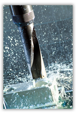
Showing posts with label Tool Making/Mould Making. Show all posts

Saturday, 9 February 2013

Tool Design - Sprue bush & locating ring


SPRUE BUSH and LOCATING RING

when you choose sprue bush, make sure you was know the diameter ball nozzle of plastics injection (SR) is less than diameter ball (SR - at picture below indicate by R)

if diameter R of Sprue bush to little than nozzle SR diameter, that will not good match or touching, if injection machine working plastic flash will out between nozzle and sprue

LOCATING RING

some mold designer usually use Locating ring to prevent unmatching nozzle of injection machine, before choose inside diameter of locating ring, we must know the outer diameter of nozzle that will touch with locating ring, at the picture below written in purple

Red color indicating flow of plastic material, from this picture we can take a conclusion that the picture is 2plate type of mold, look at picture there is no runner plate, and the gate type is side gate


Z pin Ejector

is used to make the runner ( RED COLOR) still adhere in core side when mold open and take the product, then Z pin will push the runner together with other ejectors

Tuesday, 4 December 2012

Tool Design - BASICs of PLASTIC MOLD..(Feed System)Part-3


Runner system, flowing part of plastic injection


Runner System Construction 

Sprue
sprue will contact first time with melt plastic, at the injection process, sprue always contact with nozzle from the injection machine, so consider when design the sprue consider the ball radius of nozzle, make sure it isn't make undercut on sprue.The dimensions of the sprue depend primarily on the dimensions of the molded part in particular the wall thickness, too little sprue will make sprue cold faster and make insufficient flow.


Main Runner
First time when design runner system, determine number of cavities, shape and gate types, then arrange the cavity layout,at the multi cavity of mold balancing of runner is important, balancing ensures virtually equal flow of plastic trough each gate.
To achieve balancing runner layout must be though,

Sub Runner
this part will continues flow from main runner until the gate, the dimension of sub runner and how much sub runner system will be, is very depending on how much cavity of the mold, and how the layout, what the layout use herring bone, H type, or star type. at the picture above use H type runner layout.

Cold Slug
when runner layout bent, clod slug may be required to continue plastic flow of better quality to the cavities.The cold slug well helps the flow of material through the runner system by stopping colder, higher viscosity material moving at the forefront of the molten mass entering into the cavity.The length of the well is usually equal to or greater about 1,5-2 time than the runner diameter.

Gate
Basic purpose of the gate is to limit the flow of the melted plastic, but it must allow that melted plastic flow and fill the cavity easily.
considering the fluidity of the material, gate should be made near the center of gravity of molding or the line to make flow uniform and melted material even, then make the gate thick but still considering melted plastic material, becouse thin part will cooled easily and faster.
the gate type is very various depend on part shape, mold layout, mold system, etc, here some explanation about design those gate type:
1. Direct gate
2. Side, edge gate
3. Tab gate
4. film gate
5. fan gate
6. Disc gate

Runner geometry 
they are various geometry that we can use in runner, such us
1. full round
2. half round
3. trapezoid
use full round and trapezoid shape is recommended in various mold. Half round runners are not recommended because of their low volume to surface ratio
here some area calculation of cross section of runner (source : http://www.dsm.com)


Runner dimensions 
The diameter of a runner depends on its length in addition to the part volume, part flow length, injection machine capacity, and gate size, Generally runner must never be smaller than the largest wall thickness of the product, it's usually make from 3 mm until 15 mm. picture below shown relation between runner diameter and maximum runner length (source : http://www.dsm.com)

The runner should be large enough to minimize pressure loss, yet small enough to maintain satisfactory cycle time, Large runners are not economical because of the amount of energy that goes into forming, and then regrinding the material that solidifies within them.

Runner layout 
In general they are three type of runner layout
1. "H" bridge (branching) runner system
2. Standard (herringbone) runner system (conventional runner)
3. Radial (star) runner system
look at picture below shown standard runner and H bridge type runner.


and below is star layout runner system (both bottom picture)

Balancing the runner system ensures that all mold cavities fill at the same rate and pressure, if the product have not similar product geometry, it is recommended to use mold analysis software like mold flow or C-Mold.

Wednesday, 14 November 2012

Tool Design - BASICs of PLASTIC MOLD..Part-2

Classification or types of mold injection very depend on what we need to make the plastic parts, because every parts have specific and unique design. when design molds we must see what the influencing factor like geometry, number of cavities, ejection principle, plastic material and shape of parts.

The basic classification of mold based on construction shown on picture below


1. Standard Molds
the standard mold is the most simple design, basically the standard molds is same as two plate molds construction, they divided in two side : cavity side and core side, cavity side is the side that construct to flowing plastic material from nozzle to cavity parts, basically they consist of sprue, runner.

core side construct to make shape for core, demolding system and ejection system, at this side we design ejection system.
standard mold have one parting line, and have one opening direction. this type of mold use in all kinds of plastic parts that doesn't have undercut, inner and outer screw.
Light brown color little and straight in ejection system is shown ejector pin.


2. Slide mold or Split mould

development from this mold type is the used slider parts in various molds types, basic slide mold is transfer horizontal movement of mold to vertical movement, this types of molds is used to make parts with undercut, you should see more at the post when we need slider for learn more.

3. Three plate molds
basically three plate molds has two parting line, and floating plate, floating plate support by support pin, Since the mold has two parting planes, the runner system can be located on one side of floating plate or make special plate that attach in floating plate, we called runner plate, see post about runner plate. Three plate molds are used because of their flexibility in gating location. this types of molds is flexible even use in multiple cavity.

note : floating plate also called cavity plate or plate number 3, to know more the different between two plate mold and three plate mold see the posting about Basic and Types Molds Construction

4. Split Cavity Mold
basically the split cavity is same as 2 plate standard mold, but the cavity have split block to make undercut product or external threads.


this type of mold use when the slider is not enough to make the undercut or the threads. the disadvantages of this mold is when use for little parts, the construction will difficult.

5. Mold With Screw Device
this mold special to make thread forming, the core can be rotate when demolding process, both internal or external threads can be forming by this type mold.


from those picture we can see that they have gear device, the gear will rotate when form thread.

6. Stripper Ejector Mold
this type of mold have special purpose to make a cup shape without undercut, stripper ejector will make ejection more easy, same movement and power at the product and without a lot of marks in product


Molds with complex and difficult design can be integrated or combined one to the others mold type.

Tool Design - BASICs of PLASTIC MOLD..Part-I

A mold plate is any plate required to built a complete mold, in all plate use for molds have the main requirements, they are :
1. Good corrosion resistant
2. Good Machinability.
3. Easy to clean
3. Good heat transfer.
4. Homogeneity of steel.
5. Easy ability.
6. Low Cost.

at picture below you can see 3 plate mold base type with closed position, basically 3 plate type and 2 plate type has some main plate, see explanation about mold construction type to understand more, in next post or PART-2


explanation below based on number at those picture
1. Fixed Clamping Plate or Top Plate
Holds The fixed side of the mold to attached at the fixed platen of the injection machine. at this plate will attach locating ring, eye bolt, and sprue bush.
2. Runner Stripper Plate
this plate only used in 3 plate molds type, the function is to cut resin from nozzle in top of sprue bush, and pull the runner by runner locking pin.
3. Fixed Mold Plate or Cavity plate.
use to hold cavity side of product, leader pin, support pin, Puller bolts, and Angular pin when slider attached.
4. Movable Cavity Plate or Cavity plate
it used to attach core side of product, return pin, leader bush and slider core if needed.
5. Back up Plate or Support plate
used to support cavity plate, attach the hole for return pin's spring, and cooling channel when in cavity plate can not make it.
6. Spacer Block
Mounted between the movable clamping plate (bottom plate) and the movable cavity plate to give space and allow the ejector plate to move when ejecting the
part. the required length of spacer block depend on ejector stroke that needed to eject product.
7.Ejector retainer plate
to hold the ejector, Z pin, shoulder bolts,and give space to ejector leader pin and support pillar.
8. Ejector Plate
Pushes the ejector pins and return pins, connected with ejector rods.
9. Movable Clamping Plate or Bottom plate
Holds The movable side of the mold like spacer block, support plate, cavity plate and ejector mechanism to the movable platen of the injection machine.


and look at picture below, shown 3 plate molds type in opening position, but at picture below, Bottom plate or movable clamping plate is number 7, number 8 is ejector retainer plate, and number 9 is ejector plate. 

Monday, 25 June 2012

Tool Making - Certifications for Manufacturing Engineers...

Society of Manufacturing Engineers (SME) provides certifications to manufacturing engineers, which is well respected and recognized among the manufacturing industry. SME provides four certifications, viz... Certified Manufacturing Technologist (CMfgT), Certified Manufacturing Engineering (CMfgE), Lean Certification and Six Sigma Certification. In this blog i will cover CMfgT and CMfgE.
Certified Manufacturing Technologist (CMfgT): This certification tests the competencies in the fundamentals of manufacturing. Certification is useful for beginners in the manufacturing industry.  To apply for this certification one should have minimum of 4 years of combined manufacturing experience and education. Topics covered in the certification exam include basic maths, applied science, manufacturing process, manufacturing management, quality control, manufacturing economics, materials, design, computer applications and automation.
Certified Manufacturing Engineering (CMfgE): This certification showcase the knowledge in advance manufacturing and demonstrates that certified personnel has the comprehensive knowledge of manufacturing process and practices. To apply for this certification one should have minimum of 8 years of experience or 7 years of experience with CMfgT certification. For test candidate can select any one of the area - Integration & Control, Process, Support Operations and Management.

http://www.sme.org/engineering-manager-professional-certification.aspx


this links help you to get certificate as a manufacturing expert.CIPETIANS please visit and enrich your values..


Thursday, 10 May 2012

Tool Making - Where To use Milling m/c or EDM - That Is The Question? Ans for that is...


Moldmakers are under constant pressure to cut costs and production time. Determining whether high-speed milling or EDM'ing - or perhaps a combination of both - is the best option may be what makes or breaks a job.
The key is deciding which process is right for your project.
The mold and die industry today needs to respond to market demands quicker and with greater flexibility than ever before. To stay competitive, a moldmaking shop must decrease production times and costs while at the same time ensuring that quality meets the customer's expectations. An intelligent combination of high-speed milling (HSM) and electrical discharge machining (EDM) can often become a decisive factor in the race for on-time delivery. The process of choosing the appropriate technology most often depends on the specific manufacturing scenario in a mold and die shop. The goal however should be a continuous feedback of up-to-date information on all the technologies available for die making to the design engineer. This facilitates part design and enables the engineer to choose the most appropriate manufacturing technique with respect to criteria such as accuracy, cost, lifetime, etc. Carriers for this information can be features, i.e., part segments that can be used along the whole CAD/CAM process chain.

Current Situation

The three major products of mold and die making - forging dies, injection and diecasting molds and deep-drawing dies - create different constraints with regard to the application of the available technologies (see Figure 1). The flat structures and typically easy to cut materials of deep-drawing dies are usually best machined by milling. EDM has found widespread use for the production of forging dies, based on the high strengths of the materials used. However, due to the low depth of contours and relatively large concave radii, a complete machining by milling has proven to be industrially feasible and economical.
                              Figure 1: Characteristics of tools and their machining in tool and die making.
The milling of injection and diecasting molds, on the other hand, is a challenge. Deep slots (e.g., for ribs or webs) and small radii can only be machined using slim and, consequently, chattering tools, reducing process control and stability} (see Figure 2). Additionally, economically viable feeds and speeds are only achieved for high spindle speeds that are usually not available in the standard mold and die shop. It is thus necessary to continuously monitor the development of EDM and milling, redefining their technological and economical barriers, to be able to make an optimum choice for machining.
                             Figure 2: High-speed machining of an injection mold with slim milling tools.
Besides geometric constraints, other factors such as material, function, surface quality or subsurface damage of a tool influence the technology decision between HSM and EDM(see Figure 3). Especially when these two techniques are used in combination, their respective influence on the mold's surface has to be considered, since varying adhesion for coatings or problems with lacquering of the molded parts may be the result.
                                               Figure 3: Mold requirements and related process planning.

Using Features to Decide Which Technology to Use

The decision for a certain technology is most often based on personal background and not on the actual technological potentials, limits and interdependencies. To convey this information in an objective manner to the design, process planning and manufacturing engineers, a structural approach is needed. Implementation can be achieved through technology features that combine information about part requirements with suitable manufacturing alternatives. We understand technology features to be a group of coherent geometrical primitives that can be associated with a certain method of production or technology. Features in general can be used along the whole product development and production chain - in the design phase, during function analysis and during assembly. In manufacturing, features help with production and technology planning.7
If technology features are to be used in mold and die making, each feature has to be coupled to a machining sequence. Adding to the complexity of the task of building up such a sequence, the geometries to be created appear inverted at the tool. Even though CAD/CAM systems are becoming more powerful and versatile, a fully automatic recognition of features, together with the calculation of an optimized machining sequence (taking various technologies into account), could not yet be implemented. Some systems do offer automatic identification of grooves and slopes, but do not include functionality to help with the milling/EDM decision, which would require extensive surface and volume analysis over the whole die. However, for now features can be created interactively and coupled with technology information and may then be used for process planning.

A Practical Example

Looking at the high-speed milling and EDM technologies, a decision has to be made whether a complete machining can be done by either one of the processes or if an intelligent combination will yield an optimum with respect to quality, time and cost. For the example shown in Figure 4 - a detail of a complex injection mold with narrow grooves of different depth and a small draft angle - three manufacturing alternatives as discussed above were compared. A complete machining by milling was impossible due to the grooves' depths; a complete machining by EDM would have been too time-consuming. A combination of high-speed milling down to a groove depth of 30 mm with a subsequent EDM proved to be the most efficient machining alternative.
                                      Figure 4: Feature-based technology planning for a groove. 
The data gathered on machining time, cost and feasibility was fed back into a database, along with data of numerous other, similar experiments (see Figure 5). Now, with the selection of a geometry in the CAD/CAM system, e.g., a deep groove, the system suggests a machining sequence, including information on the result to be expected and the relative cost, as well as additional processing constraints that may be of relevance (see Figure 6). For the example shown, the database suggests a technological feasibility limit for milling of lkr = 20 mm for the length of the milling tool and R = 0.25 D 0.5 mm for its radius (Figure 5).
                                 Figure 5: Technology database with material and geometry information.
                           Figure 6: Machining alternatives retrieved from the technology database for a certain feature.
The actual use of the CAD/CAM system's suggestion for machining depends on the specific situation of a company concerning workload, scheduling or hourly rates. Also, some restrictions exist with respect to machine availability and their specifications. For milling machines, restrictions can result from speeds, feeds, spindle power, acceleration, stiffness, etc.; for EDM machines, these limiting parameters could be generator power, planetary radius, contour control and others. Of course, the database feeding the CAD/ CAM system with technology information can be tailored to reflect the resources actually available; however, a continuous monitoring of technological development should always be established to make sure that innovations are implemented early to stay on the competitive edge.

An Integrated Milling/EDM Cell

However, using features to come up with optimum process chains is not fully effective in a conventional manufacturing environment. Considering that, even for small molds, sometimes as many as 300 electrodes are needed, an efficient realization of the manufacturing sequence is equally important. An integrated milling/ EDM cell that is being developed at the Fraunhofer Institute for Production Technology IPT jointly with an industrial consortium may turn out to be the most economic approach to addressing the manufacturing, quality and material flow issues. The cell consists of a milling machine, an EDM machine, a workflow management system, computers for NC data generation, a metrology station for intermediate and final quality control and a pallet handling system, with all stations being connected to a central database (see Figure 7 and 8). Typical errors resulting from numerous setups of workpieces and electrodes are avoided by using the palleting system. An additional advantage is that adjustments of workpieces and electrodes are done on stations separate from the EDM and milling machine, decreasing machine down times. Furthermore, the pallet racks and handling system allow for unmanned shifts, increasing the overall economics of the cell. The computer-assisted workflow management facilitates control of the cell and introduces flexibility in case of unforeseen changes or repair work.
                                                                Figure 7
                                                    Figure 8: Integrated milling/EDM cell.

Conclusion

New developments in machinery, process technology and software help tool and die makers become more efficient through simulation and automation. Using features that retain a company's process know-how during tool design and process planning ensures that optimized manufacturing sequences are laid out. If these are realized within an integrated EDM/ milling cell, a maximum productivity gain can be expected. Still, the technical expertise of the manufacturing engineers and experience gained over many years can not be replaced by such a system and represents the main capital of the mold and die shops.

Tuesday, 24 April 2012

Tool Making - How to Choose the Correct Ejector Pin?


HOW TO SELECT EJECTOR PIN:-

   There are many different kinds of ejector pins in the market nowadays and it is a challenge for users to select the correct ones. In most cases, selecting an inappropriate ejector pin is wasting resources andcreates inefficiency in production.
Many of us understand the importance of material and related hardness when selecting an ejector pin. However, in this article, we will focus on another important factor and that will be the working temperature.

Working Temperature

Working temperature is crucial because it affects the lifetime or durability of an ejector pin. For example, if the working temperature is high and the ejector pin being used is made for a low working temperature environment, then the ejector pins will certainly not last long.
In the market, there are three common types of ejector pins: (1) through hard pins, (2) nitride H13 pins and (3) the newly developed black ejector pins. All of these pins are excellent to use; however, each has its own characteristics and is designed to be used in a specific environment.
Through Hard Pins
                                      The design of the through hard pins involves the same hardness throughout the diameter of the ejector pin. With this characteristic, the ejector pin can last much longer in working temperatures below 200oC. It is mainly suitable for plastic injection molds.
Nitride H13 Pins
                                 If the working temperature goes beyond 200oC, then nitride H13 pins will be a much better fit. The reason is that the surface of these pin has a hardness of HRC 65 to 70, which can lead to a much better life expectancy in high working temperatures. These pins are best for die casting.
Black Ejector Pins
                                    Nitride H13 pins are not suitable for working temperatures that exceed 600oC, so black ejector pins were developed as an option. These pins have a special black surface coating treatment on the entire pin that can sustain working temperatures up to 1,000oC. Also, the special black surface treatment provides additional self lubrication to the ejector pin, making it an excellent fit for automobile injection molding. These pins are suitable for most working temperatures, but the cost of such a pin is higher.
 

Summary

                          From the above comparison, it is evident that different types of ejector pins are suitable for different environments, which is why working temperature is a necessary factor to consider before your final selection. This will also apply to ejector sleeve and ejector blade selection.

Wednesday, 11 April 2012

Tool Making - Six Points You Must Want to Know about High-Feed Milling...

                                          A look at why the benefits of high-feed milling can significantly outweigh the potential challenges.High-feed milling focuses on removing as much material as possible in the shortest amount of time. It’s a process that’s been around for a while and can open doors to more lucrative business opportunities. Unfortunately, some manufacturers have moved away from the process due to what they consider reliability concerns. And it’s true, if not applied properly, high-feed milling can create some unfavorable results.

                                           For those willing to take the leap, the benefits of high-feed milling can significantly outweigh the potential challenges. The process offers amazing productivity, nearly triple the metal removal rate of conventional methods, and increases tool life. However, there are several things you must know in order to make high-feed milling successfully work for you.

1.    Machine Tools
                                    Rigid, highly capable machine tools are a must because the cutters run at high feeds, which require the machine and the control to keep up with these demands. New equipment is a lot more advantageous when dealing with high-feed milling technology. It’s possible to apply new high-feed mills on older machines, but the process works best with large cutters because the feeds and speeds are not as accelerated.

2.    Inserts
                     Trigon-style inserts provide the lowest possible lead angle over round or square inserts. Low lead angles produce a much thinner chip, which in turn, requires higher feedrates to maintain proper chip thickness for the insert geometry. The lower lead angle also directs the cutting forces in the axial direction, pushing up into the spindle, which is more stable and easier on the machine. Higher lead angles create thicker chips requiring less adjustment in feedrate. They also produce more radial force causing vibration and stress on the spindle bearings.
High-feed cutters that use trigon-style inserts, providing the lowest possible lead angle over round or square inserts to direct cutting forces in the axial direction, which is more stable and easier on the machine

3.    Insert Grade
                              Make sure you have the right insert grade for your job because you don’t want your tool to fail prematurely, especially if you’re performing a lights-out operation. Choosing the correct insert grade for the type of material you are machining can increase tool predictability, resulting in fewer tool changes, less rejects and less reworking. 

4.    Machining Application
                                                   Not every machining method is created equal. While high-feed mills with long overhangs are great, for high-speed options for milling processes, you need to remember you can’t run them as fast as you would tools with shorter overhangs without adding specialized vibration dampening toolholders or reducing cutting speed. When a tool with long overhang operates faster than it should, you can experience increased vibrations, causing insert chipping and premature insert failure.   
 High-feed mills well suited for plunge milling because they are free cutting and provide efficient chip evacuation.

5.    Programming
                                   Optimize the cutter path through proper programming, so you don’t put any unrealistic demands on the cutting tool. For example, when you are in a mold and come to a corner, changing directions without using a smooth transition is very hard on a tool because it creates a large angle of engagement. A good rule of thumb is to program an arc that is 50 percent larger than the cutter diameter. If using a 2.0” cutter, program a 3” diameter arc.  Programming an arc in pocket corners reduces the angle of engagement and avoids overloading the cutter. Machine tools can also have problems in this area because several calculations are involved in generating an arc. If the machine tool can’t properly calculate the arc, the toolpath can become erratic.
Where drilling would draw too much power on low-power machines, this high-feed mill offers the option of instead creating holes by helical ramping.

6.    Engaged Tools
                                      Keep your high-feed mills as engaged as possible across the full diameter or less than half the insert width. One of the reasons these mills work so well is because their cutting forces are directed at the machine spindle in the axial direction to create balance. If you use the same cutter and only engage it 50 or 60 percent of the diameter, you will experience push and increased vibrations because the cut is unbalanced.

Wednesday, 21 March 2012

Tool Making - Idea for Reduce Production Costs and Maintain Precision..

                                              One of the greatest challenges facing moldmakers today is reducing production costs while still maintaining high levels of precision.  Moldmakers have frequently relied on one of two technologies to help them accomplish this: hot runner systems or mold base quick-change systems. Hot runner systems produce cleaner, more precise parts and eliminate material waste. Mold base quick-change systems reduce the time it takes to swap out molds and enable molders to produce different parts in the same system. Both technologies have distinct advantages, but recent advancements now enable moldmakers to combine all the benefits of mold base quick-change and hot runner technology in one system. 
   
A combined mold base quick-change/hot runner system allows molders to substitute different mold inserts into a mold and produce a variety of parts in the same system with little downtime.
                                               
              By understanding the potential of this type of system, designers can now engineer the cost-saving features of both products into a mold, and as a result, significantly reduce the cost of part production. This article will focus on the benefits of combining these systems in mold designs, because the more moldmakers know about this technology, the better they will be able to improve their offer to molders.

The Mold Base
                                   The mold base quick-change system approach is based on an unlimited number of companion insert molds that are easily interchanged within a single quick-change frame. The frame remains in the molding machine during mold changeovers, resulting in increased uptime and cost reductions. It works with any standard mold base in any molding machine up to 500-ton capacity.

The frame is installed without modifying the machine. Standard mold bases equipped with companion ear plates are interchanged within this adapter frame. Just one adapter frame accommodates an unlimited number of standard mold bases. While these frames can remain in the machine indefinitely, they are easily transferred to other machines. No other special mounting hardware is required.

This system is based on a unique slide and clamp approach to mold changeovers. Standard mold bases equipped with ear plate sets simply slide in and out of the quick-change adapter frame. Just one adapter frame is needed for each molding machine selected for quick-change operation.

     
A mold base quick-change system approach uses a frame that remains in the molding machine during production changeovers. The frame is installed without modifying the machine and just one adapter frame accommodates an unlimited number of standard mold bases.

                            For installation simply clamp the quick-change adapter frame to the platens of the molding machine. Companion ear plates are bolted to the standard mold bases to be interchanged in the machine. Both the machine and the standard mold bases are now ready for production changeovers in less than 10 minutes.

The Hot Runner
                          Hot runner systems were created out of a need to mold plastic parts better, faster and at a lower cost. When they are selected, installed and working properly, they do just that—delivering better part quality, faster speeds, less scrap, lower labor costs, higher-volume production and increased efficiency. However, achieving the maximum potential requires proper knowledge, planning, design and execution.

One of the primary benefits of hot runner systems is their speed. The cost savings associated with producing products faster is a driving force behind the growing demand for hot runners. Fractions of a second in cycle time add up quickly and can make a large difference to the bottom line.

Mold base quick-change/hot runner systems are particularly well-suited for increasing efficiency in the production of automotive, medical, electronic and small appliance parts, as well as for a variety of other applications.

                                       Hot runners also cut cost by greatly reducing waste. The very nature of the technology eliminates runner waste and any costs necessary to re-grind or dispose of scrap. The technology also enables a variety of increased process efficiencies, as well as the capability for extreme precision. An example of how exact hot runner systems can be is the electric valve gate. This technology uses variable pin positioning in 0.001” increments, giving an ultimate level of control to molders.

The Combination
                                By using a combined mold base quick-change/hot runner system, a molder is able to quickly swap different mold inserts into a mold and produce a variety of parts in the same system with minimal downtime. The systems are especially well-suited for increasing efficiency in the production of automotive, medical, electronic and small appliance parts, as well as for a variety of other applications.

With a traditional mold base and hot runner setup, a molder needs a new mold and new hot runner for each new part number. But by combining these powerful technologies, one can create an infinite number of different parts with just one hot runner and a quick-change system. For example, instead of using 10 separate mold and hot runner systems to create 10 different parts, a molder can use one hot runner with a mold base quick-change system and create those same 10 parts, saving more than 50 percent on costs.

Additionally, since the system incorporates hot runner technology, it keeps the polymer melt more uniform during the injection molding process. The hot runner precision produces cleaner, more accurate parts, which is especially beneficial for more complex part designs. The hot runners, compatible with any hot runner nozzles, also reduce material waste, cycle times and other costs.


Summary
                          Mold base quick-change/hot runner systems provide many advantages for moldmakers and molders alike. However, they’re not always the right solution. This is especially true, if the parts being produced aren’t similar in size and shape. The best way for moldmakers and part designers to determine whether these systems are suitable for a specific application is to work closely with a mold supply partner. Through collaboration, planning and implementing this technology, when appropriate, moldmakers and molders can experience all the benefits of both quick change and hot runner—reducing production costs and ensuring the highest levels of precision.